
Choosing the correct Pipe Elbow size involves more than matching two pipe diameters. A fitting may look suitable on a workbench, yet fail to fit once insulation, flanges, or nearby valves are installed. In practical projects, small dimensional mistakes can create stress, turbulence, leakage, and expensive rework.
This guide presents seven useful tips for selecting the right elbow size. It considers nominal pipe size, outside diameter, wall thickness, bend radius, pressure rating, temperature, material, and connection type. You will also see why center-to-end dimensions matter. A long-radius elbow may reduce flow resistance, while a short-radius design can save space. Neither option is automatically better. The correct choice depends on the system layout and operating conditions.
Check the details.
Reliable selection should follow recognized specifications, such as ASME B16.9 or EN 10253, when they apply. However, standards alone do not replace project drawings, manufacturer data, or engineering review. I have seen installations where the diameter was correct, but the elbow’s schedule or end preparation was wrong. That mistake delayed welding and disturbed the planned pipe alignment. Even experienced teams can overlook access space or thermal movement. This is where careful measurement helps. Compare the fitting against actual pipe samples, confirm pressure and temperature limits, and review the supplier’s dimensional chart before ordering. The process is not perfect, but a written checklist makes weak assumptions easier to find. A well-selected Pipe Elbow supports safer flow, cleaner installation, and more dependable long-term performance.
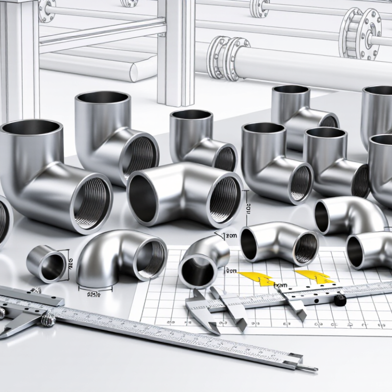
Choosing an elbow starts with its type, not its diameter. A 90-degree elbow changes direction sharply, while a 45-degree elbow usually reduces turbulence and pressure loss. Long-radius elbows provide smoother flow than short-radius designs. That difference matters in pump discharge lines. I have seen crowded pipe racks push installers toward short-radius elbows, even when flow performance needed more attention.
Check the connection method carefully. Butt-weld, socket-weld, threaded, and flanged elbows follow different dimensional rules. ASME B16.9 generally covers wrought butt-welding fittings, while ASME B16.11 covers forged socket-weld and threaded fittings. Flanged connections require compatible flange dimensions and pressure classes. Do not match an elbow by nominal size alone. Verify NPS or DN, schedule, wall thickness, center-to-end dimensions, and pressure-temperature ratings. Small details matter.
Review the governing project standard before ordering. Regional specifications may use different metric or imperial references. Confirm the pipe’s material, corrosion allowance, operating temperature, and fluid compatibility. A stainless elbow cannot automatically replace a carbon-steel fitting. It may fit physically, but the service conditions can disagree. Measure the available space, calculate the bend radius, and check the manufacturer’s certified drawing. I still recheck these points before fabrication. One overlooked dimension can create a costly alignment problem.
Measuring pipe diameter, wall thickness, and connection requirements prevents many installation problems. Measure the outside diameter with a calibrated caliper, not by visual estimation. For large pipes, wrap a flexible tape around the circumference and divide by 3.1416. Record the nominal size separately. Nominal size and actual diameter are not always identical. Check the wall thickness with an ultrasonic gauge or a cut sample. A small error can change the required elbow schedule. It happens.
Match the elbow to the pipe’s pressure class, temperature range, and material. Confirm whether the connection is threaded, socket-welded, butt-welded, or flanged. Each type needs different dimensions and preparation. Inspect flange face details, gasket space, and bolt-hole alignment before ordering. Measure the available bend radius, especially near pumps, valves, and narrow supports. A short-radius elbow may fit physically but create higher flow resistance. Review the engineering drawing and applicable piping standard with a qualified technician. I have seen accurate measurements fail because corrosion allowance was ignored. Allow space for insulation and future maintenance. Check alignment twice. Small gaps become expensive corrections during installation. When uncertainty remains, document the measurements, photograph each connection, and request a technical review before cutting the pipe.
Choosing the right pipe elbow size starts with flow rate, not the pipe drawing. Calculate the design flow, then check velocity, pressure loss, and operating temperature. Crane Technical Paper No. 410 explains that fittings create local resistance, commonly expressed through loss coefficients. A tight-radius elbow usually causes more loss than a long-radius elbow. That difference can increase pump duty and operating cost. Keep the flow stable.
Use ASME B16.9 for butt-weld elbow dimensions and ASME B16.5 for flanged pressure classes. These standards help verify outside diameter, wall thickness, face dimensions, and pressure-temperature ratings. Do not assume a matching nominal size provides matching performance. For water systems, many engineering guides place practical velocity near 1.5–3 m/s, but the correct value depends on noise, erosion, fluid viscosity, and project limits. Check the actual pressure drop with the manufacturer’s tested coefficient or a validated calculation.
I have seen neat layouts fail because one elbow was treated as a straight pipe. It was not. Leave room for inspection and thermal movement. Confirm the minimum pressure at the elbow outlet, especially near pumps or control valves. A larger elbow may reduce turbulence, yet it can create unnecessary material and installation costs. The best choice is not always the largest size. Recheck the assumptions. Small errors in flow data can distort the entire selection.
Practical reference for selecting a 90° pipe elbow using flow rate, velocity, pressure loss, geometry, and service conditions.
| Tip | Selection Dimension | What to Check | Recommended Practice |
|---|---|---|---|
| 1 | Confirm the fluid and operating service | Identify the fluid, temperature, viscosity, density, solids content, corrosiveness, and whether the service is liquid, gas, or vapor. | Use fluid properties at the actual operating temperature. A size that works for water may not provide the same velocity or pressure drop for oil, gas, or slurry. |
| 2 | Set a suitable velocity range | For many general water systems, an initial design range of approximately 1–3 m/s is commonly used. | Keep velocity high enough to maintain practical pipe sizing, but low enough to limit noise, erosion, water hammer, and excessive friction loss. Final limits depend on the system and fluid. |
| 3 | Match nominal size to actual internal diameter | Nominal pipe size is not the same as the flow area. Wall thickness and pipe schedule change the internal diameter. | Calculate flow area from the actual inside diameter: Q = A × v. Check the elbow bore against the connecting pipe to avoid a sudden restriction. |
| 4 | Check pressure and temperature ratings | Review design pressure, design temperature, material strength, wall thickness, and applicable dimensional and pressure standards. | Select an elbow rating that exceeds the design conditions after all temperature derating, corrosion allowance, and joining-method limitations are considered. |
| 5 | Choose the bend radius | Long-radius elbows generally create less turbulence and lower pressure loss than short-radius elbows of the same nominal size. | Use a long-radius elbow when space permits and energy efficiency or lower noise is important. Use a short-radius elbow only when layout constraints or the design standard permit it. |
| 6 | Estimate local pressure loss | Elbow loss depends on velocity, bend radius, elbow angle, surface condition, and the loss coefficient K. | Estimate minor loss with ΔP = K × ρ × v² ÷ 2. For a preliminary water calculation, a smooth long-radius 90° elbow may use an approximate K-value near 0.2; use project-specific data for final design. |
| 7 | Verify installation and system behavior | Check support spacing, alignment, straight-pipe requirements, vibration, thermal expansion, drainage, venting, and accessibility. | Confirm that the elbow does not create an undesirable flow disturbance near pumps, meters, control valves, or other sensitive equipment. Follow the relevant piping code and project specification. |
| Nominal Pipe Size | Reference Inside Diameter | Approximate Flow at 1 m/s | Approximate Flow at 3 m/s | Estimated 90° Long-Radius Elbow Loss at 3 m/s | Typical Preliminary Use |
|---|---|---|---|---|---|
| NPS 1 | 26.64 mm | 0.56 L/s 2.00 m³/h | 1.67 L/s 6.02 m³/h | 0.90 kPa K ≈ 0.2, water at 20°C | Small branches, instrument lines, and low-flow utility services |
| NPS 1½ | 40.89 mm | 1.31 L/s 4.73 m³/h | 3.94 L/s 14.19 m³/h | 0.90 kPa K ≈ 0.2, water at 20°C | Small process branches and utility distribution |
| NPS 2 | 52.48 mm | 2.16 L/s 7.79 m³/h | 6.49 L/s 23.36 m³/h | 0.90 kPa K ≈ 0.2, water at 20°C | General-purpose water and process piping |
| NPS 3 | 77.93 mm | 4.77 L/s 17.17 m³/h | 14.31 L/s 51.52 m³/h | 0.90 kPa K ≈ 0.2, water at 20°C | Medium-flow process, cooling-water, and utility lines |
| NPS 4 | 102.26 mm | 8.22 L/s 29.59 m³/h | 24.65 L/s 88.74 m³/h | 0.90 kPa K ≈ 0.2, water at 20°C | Higher-flow distribution and process systems |
| NPS 6 | 154.08 mm | 18.64 L/s 67.10 m³/h | 55.91 L/s 201.28 m³/h | 0.90 kPa K ≈ 0.2, water at 20°C | Large utility headers and industrial process lines |
| NPS 8 | 202.72 mm | 32.28 L/s 116.20 m³/h | 96.83 L/s 348.60 m³/h | 0.90 kPa K ≈ 0.2, water at 20°C | Large cooling-water, distribution, and transfer systems |
| NPS 10 | 254.51 mm | 50.88 L/s 183.17 m³/h | 152.63 L/s 549.52 m³/h | 0.90 kPa K ≈ 0.2, water at 20°C | High-capacity headers and low-pressure-drop systems |
| NPS 12 | 303.18 mm | 72.18 L/s 259.85 m³/h | 216.53 L/s 779.51 m³/h | 0.90 kPa K ≈ 0.2, water at 20°C | Very high-flow transfer and distribution headers |
Engineering note: The flow ranges are calculated from reference Schedule 40 inside diameters and velocities of 1–3 m/s. Pressure-loss values are preliminary estimates for water at approximately 20°C using an illustrative long-radius 90° elbow loss coefficient of K ≈ 0.2. Actual results vary with elbow geometry, surface roughness, fittings, fluid properties, temperature, and the selected pipe standard.
Pipe elbow sizing is not only about matching the pipe diameter. In field work, a 90-degree elbow can look correct but still create excessive pressure loss. Check the nominal size, wall thickness, bend radius, and connection type against the actual piping layout. A short-radius elbow saves space, yet it may increase turbulence and stress near pumps or valves.
Material compatibility deserves careful attention. Compare the pipe, elbow, gasket, and joining method as one system. Stainless steel may suit clean water, but chloride-rich water can still cause localized corrosion. Carbon steel may work in dry service, but moisture and acidic condensate can damage it quickly. Review fluid chemistry, pH, chloride levels, solids, and expected flow velocity. Do not rely on a familiar material without checking current service conditions.
Temperature changes the decision. Record normal, minimum, and maximum operating temperatures, including cleaning or steam cycles. An elbow rated for ambient service may weaken or deform at elevated temperatures. Also confirm pressure ratings at the real operating temperature, not only at room temperature. Check applicable engineering standards and request material certificates when traceability matters. Inspect the inner surface for roughness, weld quality, and signs of pitting before installation.
I once trusted a neat calculation that missed a temperature surge. The result was a costly redesign. A clean spreadsheet can still hide a bad assumption.
7 Tips for Choosing the Right Pipe Elbow Size?
Pipe elbow size is not just a diameter decision. Begin by matching the elbow’s nominal size with the connected pipe. Then verify the actual outside diameter and wall thickness. Check whether the connection uses threaded, socket, or welded ends. These details prevent costly mismatches. Measure twice. Even experienced installers can trust an outdated drawing, so record every measurement on site.
Fit must be tested in the real installation area. Measure the center-to-face dimensions before ordering. Leave enough clearance for tools, insulation, supports, and future maintenance. Check nearby valves, flanges, and structural surfaces. A tight bend may fit on paper but fail during assembly. Dry-fit the elbow when practical. Never force a connection into alignment. I once allowed enough room for the elbow, but not the wrench. That small oversight delayed the installation.
Industry specifications should guide the final choice. Confirm pressure ratings, temperature limits, material compatibility, and required bend radius. Review project drawings and applicable piping standards together. Do not rely on size alone. Some systems require specific wall thicknesses or testing procedures. Ask a qualified engineer when specifications conflict. Keep measurement records, inspection notes, and supplier documents with the project file. My own checks are not flawless, and a second review often catches a missing clearance or an incorrect size.
