A Swing Check Valve protects piping by allowing fluid to move in one direction and stopping it from returning. Its design is simple, but its responsibility is serious. Inside the body, a hinged disc responds to flow. Forward pressure lifts the disc from its seat. Reverse flow pushes it closed.
Valve specialist Philip L. Skousen describes the basic principle clearly: “A check valve automatically opens with forward flow and closes against reverse flow.” This short explanation captures the mechanism, but real systems demand more attention. Disc weight, hinge position, flow speed, and installation angle can change performance. A poorly selected Swing Check Valve may slam shut, create water hammer, or fail to seal tightly.
The sound matters.
In a pump room, a successful valve may produce only a brief metallic movement. A faulty one can create repeated banging through the pipework. That difference often reveals poor sizing, unstable flow, or an unsuitable installation position. Engineers should check pressure ratings, fluid compatibility, seat materials, and maintenance access before choosing a model.
This guide explains what a Swing Check Valve is and how it works. It also examines its internal parts, operating cycle, advantages, limitations, and common applications. Some explanations may seem obvious. They are not always obvious in the field. Careful inspection remains essential, because a valve that works well on paper can behave differently inside a vibrating pipeline.
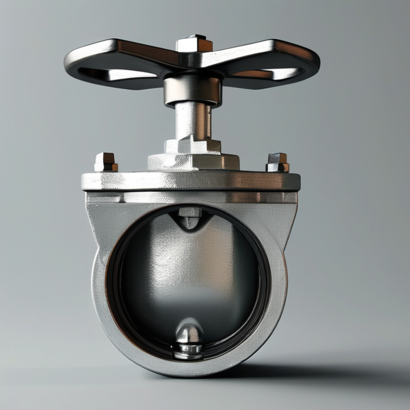
A swing check valve is a self-acting, one-way valve that prevents reverse flow in piping systems. Its central part is a hinged disc, often called the clapper. Forward fluid pressure lifts the disc from its seat. When flow slows or reverses, gravity and backpressure return the disc to its seat. The line closes without an actuator, power supply, or operator.
This design usually creates less pressure loss than lift-style check valves. It suits water, wastewater, process piping, and many pump discharge lines. However, the disc needs enough flow to open fully. Weak flow can cause flutter, noise, and premature seat wear. A 2024 MarketsandMarkets report estimated the industrial valves market at about USD 78 billion in 2023, showing the scale of valve use across industrial infrastructure. Standards such as API 6D and ASME B16.34 provide important guidance, but field conditions still matter. The simple picture is useful, but incomplete.
Tips: Install the valve with the correct flow arrow. Keep the hinge accessible for inspection. Avoid placing it where pulsating flow can repeatedly slam the disc. In pump systems, check for water hammer during startup and shutdown. In practice, a larger valve is not automatically safer. Poor sizing can create unstable operation. Review pressure, temperature, fluid cleanliness, and closing speed before selection. Exact performance depends on the valve’s materials, seat design, and installation angle.
A swing check valve uses a hinged disc to permit flow in one direction. When upstream pressure rises, the disc swings away from its seat. Fluid then passes through the open body with relatively low resistance. When flow slows or reverses, the disc returns toward the seat. Gravity, reverse pressure, and hinge design control this movement. The disc closes before reverse flow becomes severe.
Not always. The U.S. Department of Energy’s Improving Pumping System Performance sourcebook notes that pumping systems can represent about 20–25% of industrial electricity use. This makes unnecessary pressure loss worth examining. A poorly sized check valve can keep the disc partly open, creating turbulence, vibration, and extra pump demand. The International Energy Agency’s World Energy Outlook also identifies industry as a major global energy consumer, reinforcing the value of efficient fluid control.
Installation matters. A swing disc needs enough flow velocity to remain stable, but excessive velocity can cause repeated impacts. Place the valve with its hinge and flow arrow correctly aligned. Short, straight pipe sections help reduce turbulence. In wastewater lines, solids may collect around the hinge and prevent full seating. In hot-water systems, thermal expansion can increase closing forces. Inspection should check the seat, hinge pin, disc movement, and signs of water hammer. API 6D and ASME B16.34 provide recognized design and testing frameworks, but field conditions still decide performance. A compliant valve can fail early when selection ignores pulsation, orientation, or maintenance access.
A swing check valve prevents reverse flow with a hinged disc that moves freely in one direction. Its main parts are simple, but each part affects reliability. The body contains pressure and guides the flow path. The disc closes against the seat when flow reverses. A hinge pin supports the disc, while the hinge arm controls its movement. Some designs include a counterweight or lever for faster closure. Small details matter.
The seat creates the sealing line. Metal seats tolerate higher temperatures, while resilient seats can reduce leakage at lower pressures. The choice depends on fluid, temperature, pressure, and expected cycling. API 6D and ASME B16.34 provide widely used requirements for valve design, pressure testing, and materials. These standards do not replace site judgment. Real installations are messier.
A 2023 Grand View Research report estimated the global industrial valves market at more than 75 billion U.S. dollars, showing the scale of equipment used in process systems. Yet market size does not guarantee correct selection. Engineers should check flow direction, minimum velocity, pipe orientation, and water-hammer risk. A heavy disc may close slowly and cause reverse movement. A light disc may slam shut. It sounds minor. It is not. Field inspections should examine hinge wear, seat damage, corrosion, and trapped debris. The U.S. Department of Energy also identifies maintenance and leakage control as important parts of industrial energy management. A swing check valve can look healthy outside while its seat is already failing.
| Component or Feature | Primary Function | How It Works in Operation | Typical Design or Material Considerations |
|---|---|---|---|
| Valve Body | Contains the internal parts and provides the pressure boundary for the flowing medium. | Directs fluid through the inlet and outlet passages while supporting the hinge and seat assembly. | Commonly manufactured from cast iron, ductile iron, carbon steel, stainless steel, or suitable plastic, depending on pressure, temperature, and fluid compatibility. |
| Cover or Bonnet | Closes the valve body and allows access to internal components for inspection or maintenance. | Remains secured during normal operation and is removed when the disc, hinge, or seat requires service. | Usually bolted to the body with a gasket or sealing element to reduce leakage at the joint. |
| Swing Disc | Opens to permit forward flow and closes to prevent reverse flow. | Forward fluid pressure lifts the disc away from the seat. When flow decreases or reverses, the disc swings back toward the seat under gravity, reverse pressure, or both. | The disc may be metal, lined metal, or fitted with an elastomeric sealing surface. Its weight and geometry affect closing speed and pressure loss. |
| Hinge and Hinge Pin | Provide the pivot point that allows the disc to swing freely. | The disc rotates around the hinge pin as flow conditions change, without requiring an external actuator. | Materials should resist wear, corrosion, and fatigue. Proper alignment helps prevent sticking and uneven seat contact. |
| Valve Seat | Creates the sealing surface against which the disc closes. | When the disc contacts the seat, the passage is blocked and reverse flow is minimized. | Seats may be integral metal surfaces or replaceable resilient inserts. Selection depends on fluid temperature, chemical compatibility, and leakage requirements. |
| Disc-to-Seat Seal | Reduces leakage when the valve is closed. | Sealing occurs when the disc presses against the seat around the flow opening. | Metal-to-metal sealing tolerates higher temperatures and harsh service; resilient seals can provide tighter closure but have temperature and chemical limits. |
| Flow Direction Marking | Shows the permitted direction of fluid flow during installation. | The valve must be installed so that normal forward flow moves toward the side that lifts the disc open. | Usually indicated by an arrow cast, stamped, or marked on the valve body. Incorrect installation can prevent opening or cause abnormal pressure loss. |
| Gasket or Body Seal | Seals the connection between the valve body and cover. | Maintains a pressure-tight joint as the body experiences operating pressure and temperature changes. | Gasket material must be compatible with the conveyed fluid, operating temperature, and pressure. |
| Opening Mechanism | Allows forward flow without manual or powered actuation. | The pressure difference across the disc overcomes the disc’s weight and friction, causing the disc to swing open. | Opening depends on flow velocity, disc mass, hinge position, and valve orientation. A minimum flow may be needed to keep the disc open. |
| Closing Mechanism | Stops or limits reverse flow after forward flow decreases. | The disc returns toward the seat because of gravity, reverse pressure, and the valve’s own geometry. Closing before substantial reverse flow helps reduce backflow. | Rapid closure may contribute to water hammer. In some designs, a lever, weight, dashpot, or other control device is used to influence closing behavior. |
| Pressure Drop | Represents the flow resistance created by the valve when open. | Fluid changes direction and passes around the disc, producing a pressure loss that varies with flow rate and valve design. | Swing check valves generally require adequate flow to fully open and may have greater pressure loss than some axial-flow check valve designs. |
| Backflow Prevention | Protects pumps, compressors, piping, and process equipment from reverse flow. | The disc closes automatically when downstream pressure exceeds upstream pressure or when forward flow stops. | A check valve is a passive, self-acting device and does not normally provide positive shutoff equivalent to an isolation valve. |
| Installation Orientation | Ensures that gravity and flow forces support reliable operation. | Many swing check valves are installed in horizontal pipelines, while some designs permit vertical installation with upward flow. | The manufacturer’s orientation requirements must be followed. Downward vertical flow can prevent the disc from closing correctly in many designs. |
| Common Applications | Provides automatic one-way flow control in piping systems. | Operates without a handwheel, actuator, or electrical control signal during normal service. | Common applications include water systems, wastewater lines, fire-protection piping, pumping systems, process piping, and compressed-air systems, subject to service compatibility. |
| Main Advantages | Offers simple, automatic, and low-maintenance reverse-flow protection. | Uses the energy of the flowing medium rather than an external power source or operator. | Typically has a straightforward construction, but performance depends on correct sizing, suitable flow conditions, proper orientation, and regular inspection. |
A swing check valve uses a hinged disc to control one-way flow. Fluid pressure lifts the disc from its seat. Reverse flow pushes it closed. The design is simple, but installation details strongly affect performance. API 594 and ASME B16.34 provide widely used requirements for check-valve construction, pressure ratings, and testing.
The conventional swing check valve suits clean water, cooling systems, and moderate-velocity pipelines. A tilting-disc design closes faster and can reduce water hammer, although its hinge and seat require careful inspection. Flanged versions are common on large pipelines. Wafer configurations save space between flanges, but installers must verify bolt alignment and pipe support.
Horizontal installation is usually preferred. In vertical lines, flow should move upward, allowing the disc to open naturally. Downward flow can hold the disc open. That is a serious mistake. Place the valve where the disc has enough clearance to move fully. Avoid mounting it directly beside a pump discharge elbow; turbulence may cause chatter, noise, and premature seat wear.
Field experience shows that valve selection is rarely isolated from infrastructure planning. The U.S. EPA’s 7th Drinking Water Infrastructure Needs Survey and Assessment estimates $625 billion in drinking-water investment needs from 2022 to 2041. Reliable isolation and backflow protection therefore matter across aging networks. Still, a swing check valve is not a cure for every surge problem. Flow velocity, pipe slope, closing time, and maintenance access must be reviewed together. Real installations are imperfect. Test the actual system.
A swing check valve uses a hinged disc to control one-way flow. Fluid pressure lifts the disc from its seat. Reverse flow pushes it closed. No actuator is required. In practical piping work, this simple motion reduces control complexity and routine energy use.
Its main advantage is relatively low pressure loss when fully open. The broad passage also suits water, wastewater, cooling circuits, and process lines containing clean liquids. The UNESCO World Water Development Report 2024 states that agriculture accounts for about 70% of global freshwater withdrawals. That scale helps explain why dependable backflow protection matters in irrigation and pumping systems. The IEA Electricity 2024 report expects global electricity demand to grow by about 3.2% annually from 2024 to 2026. More cooling and utility piping will likely follow.
The limitations deserve equal attention. A swinging disc needs space and may close slowly. Sudden reversal can create water hammer, especially in long pipelines. Vertical installation may also be unsuitable unless the flow direction supports reliable closure. Dirty fluid can damage the seat or restrict the hinge. In field inspections, the hinge is often the weak point. A quieter valve is not automatically a safer valve. Engineers should check flow velocity, surge risk, pipe orientation, maintenance access, and the fluid’s solids content before selecting this design. My view is cautious: the valve works well in stable flow, but it can disappoint when operating conditions change.
A swing check valve uses a hinged disc that opens when fluid flows forward and closes when flow reverses. The chart summarizes common operating characteristics of swing check valves using a binary engineering comparison: 1 means the characteristic generally applies, while 0 means it generally does not.
Swing check valves are commonly selected for water pipelines, wastewater systems, pump discharge lines, cooling-water circuits, and process piping. They offer automatic reverse-flow protection and relatively low pressure loss, but they may close more slowly than spring-loaded check valves and can cause water hammer if flow reversal is sudden.