
Choosing a Cutout Electric Fuse is not simply a matter of matching voltage and current. It is a field decision involving fault levels, transformer protection, climate, coordination, and maintenance access. A small fuse mounted on a pole may face lightning, salt fog, ice, vibration, and repeated load changes. One overlooked detail can leave a feeder unnecessarily exposed.
The International Energy Agency’s Electricity 2024 report expects global electricity demand to grow by an average of 3.2% annually from 2024 to 2026. More energized networks require dependable protection at distribution points. IEC 60282-2 and IEEE C37.41 provide important guidance on high-voltage fuse performance, testing, and application. Market studies from Grand View Research also indicate continuing growth in electrical protection equipment, driven by grid expansion and renewable integration. These reports describe direction, not a substitute for engineering judgment.
Electrical-safety expert John Cadick offers a useful reminder: “Electrical safety is not an accident.” The statement applies directly to fuse selection. Engineers should verify the system voltage, continuous load, available fault current, interrupting rating, time-current curve, and transformer inrush behavior. Weather exposure matters too. A fuse that performs well in a dry laboratory may behave differently beside a coastal substation. I have seen selection guides make coordination look easier than it is. That simplification deserves caution. The correct Cutout Electric Fuse must protect equipment without creating avoidable nuisance outages. This guide explains how to compare ratings, fuse links, standards, installation conditions, and lifecycle needs before making a purchase.
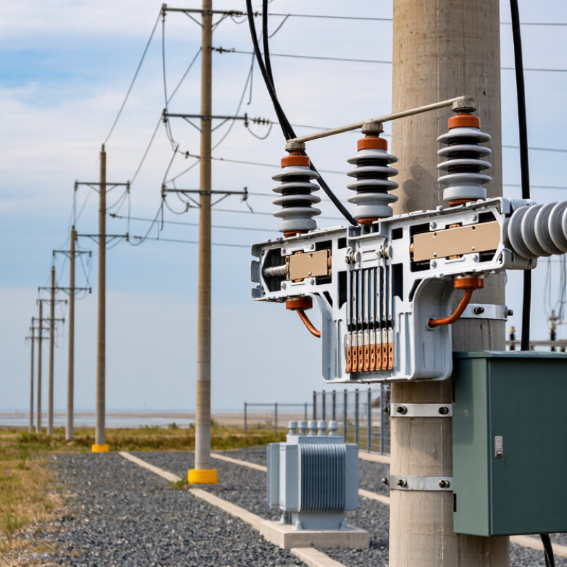
Choosing a cutout electric fuse starts with three facts: system voltage, normal current, and fault conditions. Confirm whether the circuit is AC or DC, then check its maximum operating voltage. The fuse voltage rating must meet or exceed that value. A 12 kV system should not use a fuse rated for 10 kV, even when the load appears small.
Measure the continuous load under realistic conditions. Motors, transformers, and lighting circuits can draw brief inrush current, so a fuse sized only from the running current may open unnecessarily. Check the fuse’s time-current curve, continuous current rating, and temperature derating. A cabinet reaching 55°C can reduce practical capacity. Small details matter.
The available short-circuit current determines the required interrupting rating. The fuse must safely clear that fault current without rupturing or producing dangerous external arcing. Ask for the prospective fault-current value from a qualified designer or electrician, and verify coordination with upstream and downstream protection.
A fast fuse may protect wiring well but interrupt motor starting. A slower fuse may tolerate inrush but leave conductors exposed longer. This trade-off deserves calculation, not habit. I would also recheck conductor size, enclosure conditions, and local installation requirements before purchase. The first selection is often reasonable, yet not fully correct until these details are reviewed.
Choosing a cutout electric fuse starts with the fuse type.
Expulsion fuses suit many overhead distribution applications. They clear faults by producing gases during operation. Current-limiting fuses reduce fault energy quickly and protect sensitive equipment. However, they may require different installation conditions and replacement procedures.
Check the system voltage, load current, and expected fault current before selecting one. A fuse should not operate during normal transformer energizing. It should respond when a genuine fault occurs.
Cutout style also affects safety and maintenance.
Open cutouts allow clear visual confirmation after operation. Enclosed designs offer improved protection in locations exposed to weather or accidental contact. Single-pole units are common, while gang-operated arrangements can disconnect multiple phases together.
Interrupting capacity is critical.
Select a rating equal to, or higher than, the maximum available fault current at the installation point. Never rely only on the normal load rating. Coordination with upstream and downstream protection helps isolate the smallest possible section.
Field reviews often find mismatched ratings after system upgrades. That shortcut can be costly.
Confirm test standards, installation clearances, and local electrical requirements with a qualified professional. Recheck the calculation when transformers, conductors, or network sources change.
Small details matter.
Choosing a cutout fuse begins with the protected equipment, not the fuse holder. Read transformer kVA, primary voltage, impedance, and full-load current from the nameplate. For a single-phase transformer, estimate current as kVA × 1,000 ÷ voltage. Then compare that value with the equipment maker’s permitted fuse range. Do not guess.
Operating conditions can change the correct rating. Transformer energization creates magnetizing inrush, often several times normal current for a short period. A fuse that is too small may open during switching. One that is too large may delay fault clearing. Check ambient temperature, altitude, wind, solar heating, contamination, and upstream protection coordination. Also verify interrupting capacity against the available short-circuit current. Field conditions are rarely perfect.
NFPA’s Home Structure Fires report estimated 31,400 annual fires involving electrical distribution and lighting equipment during 2015–2019, with about 470 deaths each year. This figure does not prove fuse selection caused every event, but it shows why disciplined protection matters. IEC 60269 guidance and local utility practices should support, not replace, equipment-specific data. Record the selected rating, time-current curve, ambient assumptions, and available fault current. I would revisit the choice after load growth; a comfortable rating today can become careless tomorrow.
| Equipment or Application | Typical System Voltage | Calculated Full-Load Current | Recommended Starting Fuse-Link Range | Typical Cutout Continuous Rating | Key Selection Conditions |
|---|---|---|---|---|---|
| 25 kVA distribution transformer | 11–15 kV class | Approximately 1.0–1.3 A on a 12.47 kV three-phase system | 3–6 A, subject to transformer inrush and coordination | 100 A or 200 A cutout body | Confirm transformer inrush withstand, secondary protection, and the available fault current. |
| 50 kVA distribution transformer | 11–15 kV class | Approximately 2.3 A on a 12.47 kV three-phase system | 6–10 A, depending on protection curves | 100 A or 200 A cutout body | The fuse must carry normal load and magnetizing inrush without nuisance operation. |
| 100 kVA distribution transformer | 11–15 kV class | Approximately 4.6 A on a 12.47 kV three-phase system | 10–15 A, subject to coordination study | 100 A or 200 A cutout body | Check the transformer damage curve, secondary breaker clearing time, and upstream relay coordination. |
| 250 kVA distribution transformer | 11–15 kV class | Approximately 11.6 A on a 12.47 kV three-phase system | 15–30 A, selected from time-current curves | 100 A or 200 A cutout body | Ensure the fuse clears transformer faults while allowing permissible energization inrush. |
| 500 kVA distribution transformer | 11–15 kV class | Approximately 23.1 A on a 12.47 kV three-phase system | 30–50 A, subject to available fault current and coordination | 100 A or 200 A cutout body | Verify interrupting capability, transformer damage limits, and upstream/downstream selectivity. |
| Small overhead feeder or lateral | 11–15 kV class | Use the maximum expected continuous feeder current | The next standard rating above corrected load current | 100 A or 200 A cutout body | Coordinate with downstream sectionalizers, reclosers, transformer fuses, and conductor ampacity. |
| Capacitor bank or power-factor correction equipment | 11–15 kV class | Calculate from rated kVAr and system voltage | Often higher than steady-state current to tolerate switching transients | 100 A or 200 A cutout body | Use the equipment manufacturer’s capacitor-fuse requirements and consider transient inrush and harmonic currents. |
| Motor or pump feeder | 11–15 kV class | Use motor nameplate current and starting-current characteristics | Selected above starting current duration, but below equipment fault withstand limits | 100 A or 200 A cutout body | Check locked-rotor current, acceleration time, motor protection, and coordination with the controller. |
How to Choose a Cutout Electric Fuse?
Compatibility with the fuse holder should be checked before selecting a cutout electric fuse. A similar-looking fuse may still have the wrong length, contact diameter, or mounting arrangement. Confirm the holder’s rated voltage, continuous current, interrupting capacity, and fuse-link dimensions. The electrical ratings must meet the equipment requirements, not merely the normal operating load. Review the holder and fuse manufacturer’s technical data, then verify applicable electrical standards with a qualified professional.
The installation environment matters just as much. Outdoor cutouts may face rain, dust, salt air, ultraviolet exposure, freezing temperatures, or high heat. These conditions can affect insulation, contact pressure, and fuse performance. Check the holder’s pollution level, creepage distance, and environmental rating. At higher elevations, reduced air density can also influence insulation and interruption performance. Small details matter.
Inspect the holder for cracked porcelain, corrosion, loose hardware, or darkened contacts. Do not force a fuse into a mismatched holder. It may fit poorly and create dangerous heating. A quick visual match is tempting, but it has caused avoidable field mistakes. I have also seen installations fail because temperature correction was overlooked. Measure carefully, follow the specified tightening method, and confirm clearances before energizing. Local rules and the complete equipment design should guide the final choice.
Choosing a cutout electric fuse starts with verified safety standards, not price or appearance. Check the fuse cutout against IEEE C37.41 and IEEE C37.42, or IEC 60282-2 where applicable. Confirm voltage rating, continuous current, interrupting capability, insulation level, and coordination with upstream protection. NFPA 70B (2023) promotes documented, risk-based electrical maintenance. That means recording inspection dates, operating conditions, fault history, and replacement parts. A familiar-looking fuse may still have the wrong rating. Small errors matter.
Maintenance needs should match the installation environment. Inspect hardware for corrosion, cracked porcelain, loose connections, and heat discoloration, but isolate and verify the circuit before hands-on work. Thermal imaging can reveal a hot termination; it cannot prove the fuse is safe. The U.S. Energy Information Administration’s reliability tables separate routine outages from major-event days, showing why average outage figures can hide local equipment problems. Keep spare fuse links with matching voltage, current, interrupting, and mechanical characteristics. Replacement options may include an equivalent expulsion fuse link or a complete cutout assembly, depending on damage and coordination studies. Never mix components based only on physical fit. It is tempting, but weak practice. A maintenance log can also expose repeated failures caused by wildlife, moisture, or overloaded transformers. I have seen inspection plans focus on the fuse and miss the connection beside it. That oversight deserves review.
Compare the voltage scopes of two relevant IEC standards before selecting a fuse. The correct replacement must match the system voltage, rated current, interrupting capacity, mounting arrangement, and the original fuse’s safety classification.
Safety: IEC 60269 covers low-voltage fuse-links up to 1,000 V AC or 1,500 V DC, while IEC 62271-105 covers high-voltage AC switch-fuse combinations above 1 kV and up to 52 kV.
Maintenance: Follow the equipment manufacturer’s or utility’s inspection schedule. Check for overheating, corrosion, cracked insulation, loose connections, contamination, and signs of arcing. Never replace a fuse while energized.
Replacement: Use the same rated voltage, current, interrupting capacity, physical dimensions, operating class, and system compatibility. Do not substitute a fuse solely because it physically fits.
