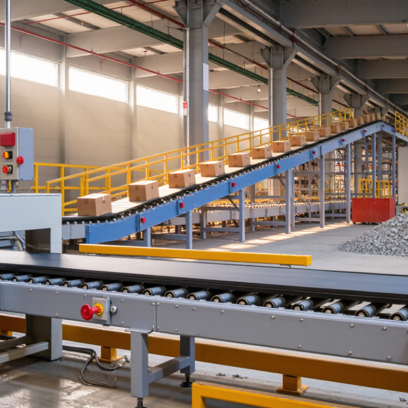
Belt Conveying Equipment is a practical material-handling system used in warehouses, mines, factories, ports, and distribution centers. It moves products along a continuous belt, reducing manual lifting and improving workflow consistency. A typical system includes a belt, drive pulley, idler rollers, frame, motor, and control unit. Each component has a clear task.
The motor turns the drive pulley. Friction then pulls the belt forward. Materials rest on the moving surface and travel between loading and discharge points. Imagine cartons passing beneath a scanner, or crushed stone moving through a dusty processing area. Belt speed, width, incline, and load weight must match the application. Poor selection can cause slipping, belt damage, spilled materials, or unnecessary energy use.
Reliable conveyor design depends on more than basic movement. Operators should inspect belt tracking, roller noise, pulley wear, emergency stops, and guarding. Maintenance records can reveal small problems before they become expensive failures. Safety procedures also matter, especially near moving belts and pinch points. This article explains how Belt Conveying Equipment works, where it fits, and what users should evaluate before installation. Real conditions are rarely perfect. Moisture, dust, temperature changes, and uneven loading can challenge even a well-designed system. Some simplified explanations overlook these details. Careful assessment remains essential.
Belt conveying equipment is a mechanical system that moves materials on a continuous belt. It commonly includes a belt, drive pulley, tail pulley, rollers, frame, and tensioning device. Its core purpose is controlled, repeatable material transfer between two points. The load may be cartons, aggregates, grain, or packaged goods. Unlike manual handling, the belt maintains a steady route and speed. It reduces walking, lifting, and unnecessary product contact.
The working principle is direct. A motor turns the drive pulley, and friction pulls the belt forward. Rollers support the loaded section, while the return section travels underneath. Guards, emergency stops, and suitable guarding distances are essential in real installations. CEMA’s Belt Conveyors for Bulk Materials, 7th Edition, stresses correct belt tension, loading, and alignment for reliable operation. A small tracking error can cause edge wear, spillage, or an unexpected shutdown. This is where simple explanations become incomplete.
Industry investment also shows why the equipment matters. The 2024 MHI Annual Industry Report surveyed more than 1,000 supply-chain professionals. It reported that 55% planned to increase investment in supply-chain innovation. Conveyors often support that investment by connecting storage, production, inspection, and dispatch areas. Their value is not only speed. It includes predictable flow, measurable throughput, and easier process observation. However, capacity figures can mislead when loading is uneven. In practice, dust, moisture, temperature, and poor maintenance may reduce performance. A conveyor that looks oversized on paper may still struggle during peak loading.
A belt conveyor moves bulk materials on a continuous loop. Its operation depends on several components working together, not only on the drive motor. The belt carries the load, while the frame keeps the conveying path stable. In practical installations, belt alignment matters greatly. A belt drifting only a few millimeters can rub against the structure, damage its edge, and increase energy use.
The head pulley transfers motion from the drive system to the belt. A tail pulley guides the returning belt and supports loading at the opposite end. Between them, carrying idlers hold the loaded belt in a shallow trough, while return idlers support the empty side. The motor and gearbox provide controlled torque, especially when the conveyor starts under load. A tensioning device maintains enough belt grip without overstretching the belt. Too little tension causes slipping. Too much tension strains bearings and splices.
Loading chutes should place material near the belt center and reduce impact from falling pieces. Skirt seals help prevent dust and spillage along the loading zone. Belt cleaners remove material that might otherwise reach pulleys and create buildup. Sensors can detect belt misalignment, speed loss, or abnormal temperature. These safeguards are valuable, but they are not a substitute for inspection. In field work, operators may focus on the motor and overlook worn idlers or uneven loading. That assumption can fail. Regular checks of pulley lagging, idler rotation, belt tension, and emergency stops provide more dependable performance.
| Component or System Parameter | Primary Role | Typical Construction or Data | How It Works in the Conveyor | Key Inspection Points |
|---|---|---|---|---|
| Conveyor Belt | Carries bulk materials or unit loads along the conveying route. | Common belt materials include rubber, PVC, polyurethane, and fabric-reinforced elastomers. Belt strength and cover grade are selected according to load, abrasion, temperature, and material type. | The belt forms a continuous loop. Its carrying strand moves material forward while the return strand travels back to the tail end. | Check for cuts, edge damage, mistracking, excessive wear, splice condition, and abnormal stretching. |
| Head Pulley | Drives or redirects the belt at the discharge end. | Usually located at the head of the conveyor. A drive pulley may use a rubber lagging surface to improve traction and reduce belt slip. | When connected to the drive unit, the pulley transfers torque to the belt through friction and rotates the belt loop. | Inspect lagging wear, belt slippage, pulley alignment, bearing temperature, and material buildup. |
| Tail Pulley | Redirects the belt at the loading end and helps define the return path. | Positioned near the conveyor inlet. It may be fixed or arranged with take-up components depending on the conveyor design. | The belt wraps around the tail pulley and changes direction from the return strand to the carrying strand. | Check alignment, bearing condition, buildup, belt contact, and clearance around the loading zone. |
| Snub Pulley | Increases the belt wrap angle around a drive pulley. | Normally installed near the drive pulley. It is smaller than the main drive pulley in many conveyor layouts. | By increasing the contact area between belt and drive pulley, it can improve traction and reduce the likelihood of belt slip. | Inspect pulley alignment, bearing lubrication, surface condition, and belt tracking. |
| Carrying Idlers | Support the loaded carrying strand of the belt. | Frequently arranged in three-roll troughing sets for bulk materials. The trough angle is commonly selected from standard conveyor design options such as 20°, 35°, or 45°. | The rolls rotate as the moving belt passes over them, reducing sag and maintaining a controlled belt profile. | Look for seized rolls, unusual noise, damaged seals, uneven rotation, and belt contact with the frame. |
| Return Idlers | Support the empty belt on the return strand. | Often consists of single horizontal rolls, although disc or spiral designs may be used where material buildup is a concern. | Return rolls keep the belt from excessive sag and help maintain a stable path back to the tail pulley. | Check roll rotation, belt sag, material accumulation, and signs of belt rubbing. |
| Impact Idlers | Absorb impact at the loading point. | Typically fitted with rubber discs or resilient sleeves over the rolls. They are installed beneath the loading zone. | The resilient roll surface cushions falling material and distributes impact forces to reduce damage to the belt and support structure. | Inspect rubber discs, frame condition, spacing, belt indentation, and loading-point alignment. |
| Drive Unit | Provides the mechanical power required to move the belt and conveyed material. | Commonly includes an electric motor, gearbox or geared motor, couplings, and a drive pulley. Power is selected from calculated belt tension and conveyor resistance. | The motor produces rotational power, the transmission adjusts speed and torque, and the drive pulley applies the resulting force to the belt. | Monitor motor current, gearbox oil level, vibration, temperature, coupling condition, and unusual noise. |
| Take-Up Device | Maintains appropriate belt tension and compensates for belt stretch. | May be a screw take-up for shorter conveyors or a gravity take-up for longer conveyors and systems requiring more consistent tension. | It moves a pulley or tensioning assembly to remove slack, maintain traction, and help prevent belt slip. | Check available adjustment travel, tension stability, pulley alignment, counterweight movement, and cable or frame condition. |
| Conveyor Frame and Stringers | Supports pulleys, idlers, belt, drive equipment, and protective components. | Usually fabricated from structural steel, formed sections, or modular aluminum profiles for lighter-duty applications. | The structure keeps the conveyor components in the required relative positions and transfers operating loads to the foundations or support legs. | Inspect welds, bolts, corrosion, deflection, structural alignment, and damaged supports. |
| Loading Chute | Guides material onto the belt and controls the loading profile. | May include replaceable liners, skirt boards, sealing strips, and flow-control sections. Chute geometry depends on material properties and belt speed. | It directs material toward the belt center and helps limit excessive impact, dust generation, and spillage. | Check liner wear, blockages, skirt sealing, material buildup, and off-center loading. |
| Skirt Boards and Sealing System | Controls material at the loading point and reduces spillage and dust escape. | Usually consists of side plates with replaceable rubber or polymer sealing strips installed along the belt edges. | The seals remain close to the belt surface while allowing the belt to move through the loading zone. | Inspect sealing pressure, belt wear caused by excessive contact, gaps, and accumulated material. |
| Belt Cleaner | Removes residual material from the belt after discharge. | Primary cleaners commonly use polyurethane or carbide-tipped blades. Secondary cleaners are often installed farther along the return path. | A blade or brush contacts the belt surface and directs carryback into a collection area or back onto the material stream. | Check blade wear, contact pressure, mounting condition, belt damage, and carryback quantity. |
| Belt Tracking System | Keeps the belt centered on the conveyor structure. | May include training idlers, guide rollers, crowned pulleys, aligned frames, and electronic tracking devices. | Tracking components apply a corrective steering effect when the belt moves toward one side. | Look for edge wear, repeated side movement, misaligned idlers, off-center loading, and structural distortion. |
| Belt Scale | Measures the mass flow rate and total material conveyed. | A typical system uses a weigh frame, load cells, a belt-speed sensor, and an electronic integrator. | The load cells measure belt loading while the speed sensor measures belt velocity; the controller calculates mass flow and accumulated throughput. | Verify calibration, zero stability, belt tension, speed-sensor condition, and material centering. |
| Safety Pull Cord | Provides a manual emergency-stop function along accessible conveyor sections. | A tensioned wire rope is connected to switches installed at intervals along the conveyor. | Pulling the cord actuates the switch circuit and stops the conveyor drive when correctly integrated with the control system. | Test switch operation, rope tension, accessibility, reset function, and electrical response. |
| Belt Misalignment Switch | Detects excessive lateral belt movement. | Uses sensing rollers or levers positioned near the belt edges. | When the belt moves beyond a preset limit, the switch can generate an alarm or stop command to prevent edge damage and spillage. | Check switch alignment, activation distance, wiring, reset function, and response during controlled testing. |
| Emergency Stop and Control System | Controls starting, stopping, interlocking, and emergency shutdown functions. | May include motor starters or variable-frequency drives, programmable controllers, sensors, alarms, and local control stations. | The control system coordinates conveyor operation and prevents unsafe starts or continued operation when a critical fault is detected. | Test emergency stops, interlocks, alarm signals, restart protection, and control-panel condition. |
| Typical Belt Speed | Defines how quickly material travels along the conveyor. | Approximately 0.5–5 m/s for many industrial applications; the suitable value depends on material, belt width, dust, loading, and transfer requirements. | Higher speed can increase conveying capacity but may also increase dust, wear, spillage risk, and stopping distance. | Compare actual speed with the design value and check for unstable material flow or excessive carryback. |
| Common Belt Width Range | Determines the available carrying area and influences conveyor capacity. | Approximately 300–2,400 mm in many general industrial systems, with larger widths used for specialized high-capacity applications. | A wider belt can carry more material at a given loading profile and speed, subject to belt strength and equipment limitations. | Confirm width compatibility across pulleys, idlers, chutes, cleaners, and loading equipment. |
| Material Flow Capacity | Describes the amount of material moved per unit of time. | Usually expressed as t/h for bulk solids or units/min for packaged products. Capacity depends on belt width, speed, trough profile, loading cross-section, and bulk density. | The belt continuously transports material, allowing a steady flow between loading and discharge points. | Check actual throughput, loading consistency, belt scale readings, spillage, and motor loading. |

What Is Belt Conveying Equipment and How Does It Work?
Belt conveying equipment moves bulk or packaged materials along a fixed route. An endless belt carries the load over supporting rollers. An electric motor turns the drive pulley, while friction pulls the belt forward. The belt then travels across carrying idlers and returns beneath the frame. It is a simple motion. Belt width, speed, and load weight must match the material and operating conditions.
Material usually enters through a controlled loading chute. Skirting helps keep it on the belt, while impact rollers reduce shock from falling material. A tensioning device keeps the belt tight enough for steady movement. If tension is too low, the belt may slip or wander. At the head pulley, the belt changes direction and releases material into a bin, truck, or another conveyor. Clean transfer matters.
In practical inspections, technicians check tracking, roller rotation, belt wear, and material buildup. Moisture and fine particles can change friction and encourage sticking. A small alignment error can spread across a long conveyor. No conveyor runs perfectly. Designers sometimes focus heavily on capacity and overlook access for cleaning. That mistake can increase downtime and make routine maintenance harder. Operators also listen for unusual rubbing sounds and watch for uneven material flow. These details often reveal problems before visible belt damage appears.
What Is Belt Conveying Equipment and How Does It Work?
Belt conveying equipment moves materials along a continuous belt powered by a motor and rotating pulleys. Rollers support the belt and reduce friction during transport. Its design seems simple, but small changes in speed, load, or incline can affect performance.
Common Types and Applications of Belt Conveying Systems
Flat belt conveyors handle cartons, parcels, and packaged goods on level production lines. Troughed belt conveyors carry bulk materials, such as grain, sand, and crushed stone. Cleated belts help move products upward without sliding. Modular plastic belts suit food processing areas because they are easy to clean and replace. Incline conveyors save floor space, although heavy loads may require stronger belts and controlled acceleration. In warehouses, conveyors connect sorting, packing, and storage zones. In factories, they support assembly work by presenting parts at a steady height. Mining and agriculture often use longer systems, where dust, weather, and belt tracking demand careful planning.
Tips: Match the belt surface to the material. Check tension and alignment regularly. Keep emergency stops visible. Do not assume a wider belt always improves output. An overloaded conveyor may run slowly, wear unevenly, and consume more energy. Operators should record unusual noise or belt drift before a minor fault becomes costly. Real conditions can differ from design calculations, so practical testing remains valuable.
Common belt conveyor applications and typical operating speed ranges
A belt conveyor uses a continuous belt supported by rollers or a slider bed. A motor drives the head pulley, and friction between the pulley and belt moves materials from the loading point to the discharge point. The belt then returns along the lower path for continuous conveying.
The chart shows representative engineering speed ranges. Food and parcel systems generally operate at lower speeds for product control, while quarry and mining conveyors use higher speeds to transport large volumes of bulk material. Actual operating speed depends on belt width, material properties, incline, loading rate, and safety requirements.
Belt conveying equipment moves bulk materials or packaged goods on a continuous belt. A drive pulley powers the belt, while idlers support its loaded surface. Tension keeps the belt tracking correctly. Small alignment errors matter. They can cause rubbing, spillage, or sudden belt damage.
Safe operation begins with guarding, emergency stops, and controlled access. The Occupational Safety and Health Administration requires machine guarding and lockout procedures under 29 CFR 1910.212 and 1910.147. These controls must match the actual conveyor, not a generic checklist.
The U.S. Bureau of Labor Statistics recorded 5,283 fatal occupational injuries in 2023. That figure covers all industries, but it shows why routine controls deserve serious attention.
The Mine Safety and Health Administration also continues to identify powered haulage as a significant mining hazard.
Keep hands, clothing, and tools away from nip points. Use pull-cord switches where workers can reach them quickly. Inspect belt edges, pulley lagging, scrapers, and guarding before each shift.
Listen for squealing idlers. Watch for uneven loading. These clues often appear before failure.
Efficient conveying also depends on correct belt tension, stable feed rates, and clean transfer points. Excessive tension wastes energy and accelerates wear.
Poor housekeeping creates slip hazards and hides defects. A practical weakness remains common: inspections may be documented carefully but performed too quickly. Supervisors should compare records with field conditions and question repeated repairs.